AI Worldbuilding Contest – Future Life Institute

This blog post is written by CDT Students Tashi Namgyal and  Vanessa  Hanschke.

Two Interactive AI CDT students were part of a team that won third place in the AI Worldbuilding Contest run by the Future of Life Institute along with their three non-CDT teammates. In this blog post, we would like to tell you more about the competition, its goals and our team’s process of creating the submission.

The Future of Life Institute describe themselves as “an independent non-profit that works to reduce extreme risks from transformative technologies, as well as steer the development and use of these technologies to benefit life”. Besides running contests, their work consists of running grants programs for research projects, educational outreach or engaging in AI policymaking internationally and nationally in the US.

The worldbuilding competition was aimed at creating a discussion around a desirable future, in which Artificial General Intelligence (AI that can complete a wide range of tasks roughly as well as humans) played a major role in shaping the world. The deliverables included a timeline of events until 2045, two “day in the life” short stories, 13 answers to short question prompts and a media piece.

While dystopian or utopian visions of our future are quite commonplace in science fiction, the particular challenge of the competition was to provide an account of the future that was both plausible and hopeful. This formulation raised a lot of questions such as: For whom will the future be hopeful in 2045? How do we resolve or make progress towards existing crises such as climate change that threaten our future? We discussed these questions at length in our meetings before we even got to imagining concrete future worlds.

Our team was composed of different backgrounds and nationalities: we had two IAI CDT PhD students, one civil servant, one Human Computer Interaction researcher and one researcher in Creative Informatics. We were brought together by our shared values, interests, friendship, and our common homes, Bristol and Edinburgh. We tried to exploit these different backgrounds to provide a diverse picture of what the future could look like. We generated future visions for domains that could be influenced by Artificial General Intelligence (AGI), that are often low-tech, but a core part of human society such as art and religion.

To fit the project into our full-time working week, we decided that we would meet weekly during the brainstorming phase to collect ideas and create drafts for stories, events and question prompts on a Miro board. Each week we would also set each other small tasks to build a foundation of our world in 2045, for example everyone had to write a day in the life story for their own life in 2045. We then chose a weekend closer to the deadline, where we had a “Hackathon”-like intense two days to work on more polished versions of all the different parts of the submission. During this weekend we went through each other’s answers, gave each other feedback and made suggestions to make the submission more cohesive. Our team was selected as one of the 20 finalists out of 144 entries and there was a month for the public to give feedback on whether people felt inspired by or would like to live in such worlds, before the final positions were judged by FLI.

Thinking about how AI tools may be used or misused in the future is a core part of the Interactive AI CDT. The first-year taught module on Responsible AI introduces concepts such as fairness, accountability, transparency, privacy and trustworthiness in relation to AI systems. We go through case studies of where these systems have failed in each regard so we can see how ethics, law and regulation apply to our own PhD research, and in turn how our work might impact these things in the future. In the research phase of the programme, the CDT organises further workshops on topics such as Anticipation & Responsible Innovation and Social & Ethical Issues and there are international conferences in this area we can join with our research stipends, such as FAccT.

If you are curious, you can view our full submission here or listen to the podcast, which we submitted as media piece here. In our submission, we really tried to centre humanity’s place in this future. In summary, the world we created was to make you feel the future, really imagine your place in 2045. Current big tech is not addressing the crises of our times including inequality, climate change, war, and pestilence. Our world seeks to imagine a future where human values are still represented – our propensity for cooperation, creativity, and emotion. But we had to include a disclaimer for our world: our solutions are still open to risk of human actors using them for ill purposes. Our solution for regulating AGI was built on it being an expensive technology in the hand of few companies and regulated internationally, but we tried to think beyond the bounds of AGI. We imagine a positive future grounded in a balanced climate, proper political, social and economic solutions to real world problems, and where human dignity is maintained and respected.


Understanding Dimensionality Reduction

This blog post is written by CDT Student Alex Davies

Sometimes your data has a lot of features. In fact, if you have more than three, useful visualisation and understanding can be difficult. In a machine-learning context high numbers of features can also lead to the curse of dimensionality and the potential for overfitting. Enter this family of algorithms: dimensionality reduction.

The essential aim of a dimensionality reduction algorithm is to reduce the number of features of your input data. Formally, this is a mapping from a high dimensional space to low dimensional. This could be to make your data more concise and robust, for more efficient applications in msachine-learning, or just to visualise how the data “looks”.

There are a few broad classes of algorithm, with many individual variations inside each of these branches. This means that getting to grips with how they work, and when to use which algorithm, can be difficult. This issue can be compounded when each algorithm’s documentation focuses more on “real” data examples, which is hard for humans to really grasp, so we end up in a situation where we are using a tool we don’t fully understand to interpret data that we also don’t understand.

The aim of this article is to give you some intuition into how different classes of algorithm work. There will be some maths, but nothing too daunting. If you feel like being really smart, each algorithm will have a link to a source that gives a fully fleshed out explanation.

How do we use these algorithms?

This article isn’t going to be a tutorial in how to code with these algorithms, because in general its quite easy to get started. Check the following code:

import numpy as np
import matplotlib.pyplot as plt
from sklearn.datasets import load_digits
from sklearn.manifold import TSNE

#    Load the data, here we're using the MNIST dataset
digits     = load_digits()

#    Load labels + the data (here, 16x16 images)
labels     = digits["target"]
data       = digits["data"]

#    Initialise a dimensionality model - this could be sklearn.decomposition.PCA or some other model
TSNE_model = TSNE(verbose = 0)
#    Apply the model to the data
embedding  = TSNE_model.fit_transform(data)

#    Plot the result!
fig, ax = plt.subplots(figsize = (6,6))
for l in np.unique(labels):
    ax.scatter(*embedding[labels == l,:].transpose(), label = l)
ax.legend(shadow = True)
plt.show()

/Users/alexdavies/miniforge3/envs/networks/lib/python3.9/site-packages/sklearn/manifold/_t_sne.py:780: FutureWarning: The default initialization in TSNE will change from 'random' to 'pca' in 1.2.
  warnings.warn(

/Users/alexdavies/miniforge3/envs/networks/lib/python3.9/site-packages/sklearn/manifold/_t_sne.py:790: FutureWarning: The default learning rate in TSNE will change from 200.0 to 'auto' in 1.2.
  warnings.warn(

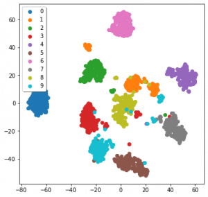
The data we’re using is MNIST, a dataset of 16×16 monochrome hand-written digits from one to ten. I’ll detail how TSNE works later on. Admittedly this code is not the tidiest, but a lot of it is also just for a nice graph at the end. The only lines we dedicated to TSNE were the initial import, calling the model, and using it to embed the data.

We still have the issue, though, of actually understanding the data. Here its not too bad, as these are images, but in other data forms we can’t really get to grips with how the data works. Ideally we’d have some examples of how different algorithms function when applied to data we can understand…

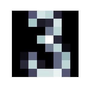
An image from the MNIST dataset, here of the number 3

Toy examples

Here are some examples of how different algorithms function apply to data we can understand. I’d credit this sklearn page on clustering as inspiration for this figure.

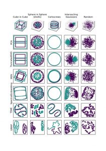
Toy 3D data, and projections of it by differerent algorithms. All algorithms are run with their default parameters.

The examples down the first column are the original data in 3D. The other columns are how a given algorithm projects these examples down into scatter-plot-able 2D. Each algorithm is run with its default parameters, and these examples have in part been designed to “break” each algorithm.

We can see that PCA (Principle Component Analysis) and TruncatedSVD (the sklearn version of Singular Value Decomposition) function like a change in camera angle. MDS (Multi-Dimensional Scaling) is a little more odd, and warps the data a little. Spectral Embedding has done a similar thing to MDS.

Things get a little weirder when we get onto TSNE (T-Stochastic Neighbours Embedding) and UMAP (Uniform Manifold Approximation and Projection). The data doesn’t end up looking much like the original (visually), but they have represented something about the nature of the data, often separating the data where appropriate.

PCA, SVD, similar

This is our first branch of the dimensionality reduction family tree, and are often the first dimensionality reduction methods people are introduced to, in particular PCA. Assuming we’re in a space defined by basis vectors V, we might want to find the most useful (orthogonal) combination of these basis vectors U, as in u = α v + β v+

V here can be thought of our initial angle to the axes of the data, and U a “better” angle to understand the data. This would be called a “linear transform”, which only means that a straight line in the original data will also be a straight line in the projection.

Linear algebra-based methods like SVD and PCA try and use a mathematical approach to find the optimum form of for a set of data. PCA and SVD aim to find the angle that best explain the covariance of the data. There’s a lot of literature out there about these algorithms, and this isn’t really the place for mathematic discussion, but I will give some key takeaways.

A full article about PCA by Tony Yiu can be found here, and here’s the same for SVD by Hussein Abdulrahman.

Firstly, these algorithms don’t “change” the data, as shown in the previous section. All they can do is “change the angle” to one that hopefully explains as much as possible about the data. Secondly, they are defined by a set of equations, and there’s no internal optimisation process beyond this, so you don’t need to be particularly concerned about overfitting. Lastly, each actually produces the same number of components (dimensions) as your original data, but ordered by how much covariance that new component explains. Generally you’ll only need to use the first few of these components.

We can see this at play in that big figure above. All the results of these algorithms, with a little thought, are seen to explain the maximum amount of variance. Taking the corkscrews as an example, both algorithms take a top down view, ignoring the change along the z axis. This is because the maximum variance in the data is the circles that the two threads follow, so a top down view explains all of this variance.

For contrast, here’s PCA applied to the MNIST data:

PCA applied to the MNIST data

Embeddings (MDS, Spectral Embedding, TSNE, UMAP)

The other branch of this family of algorithms are quite different in their design and function to the linear algebra-based methods we’ve talked about so far. Those algorithms look for global metrics — such as covariance and variance — across your data. That means they can be seen as taking a “global view”. These algorithms don’t necessarily not take a global view, but they have a greater ability to represent local dynamics in your data.

We’ll start with an algorithm that bridges the gap between linear algebra methods and embedding methods: Spectral Embedding.

Spectral Embedding

Often in machine-learning we want to be able to separate groups within data. This could be the digits in the MNIST data we’ve seen so far, types of fish, types of flower, or some other classification problem. This also has applications in grouping-based regression problems.

The problem (sometimes) with the linear-algebra methods above is that sometimes the data just isn’t that easily separable by “moving the camera”. For example take a look at the sphere-in-sphere example in that big figure above: PCA and SVD do not separate the two spheres. At this point it can be more practical to instead consider the relationships between individual points.

Spectral Embedding does just this: it measures the distance between a given number of neighbours. What we’ve actually done here is make a graph (or network) that represents the relationships between points. A simple example of building a distance-graph is below.


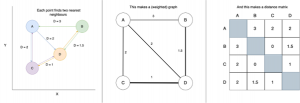
A very simple example of making a distance-graph and a distance-matrix

Our basic aim is to move to a 2D layout of the data that best represents this graph, which hopefully will show how the data “looks” in high dimensions.

From this graph we construct a matrix of weights for each connection. Don’t get too concerned if you’re not comfortable with the term “matrix”, as this is essentially just a table with equal numbers of rows and columns, with each entry representing the weight of the connection between two points.

In spectral embedding these distances are then turned into “weights”, often by passing through a normal distribution or simply binary edges. Binary edges would have [1 = is neighbour, 0 = is not neighbour]. From the weight matrix we apply some linear algebra. We’ll call the weight matrix W.

First we build a diagonal matrix (off diagonal = 0) by summing across rows or columns. This means that each point now has a given weight, instead of weights for pairs of points. We’ll call this diagonal weight matrix D.

We then get the “Laplacian”, L = D-W. The Laplacian is a difficult concept to summarise briefly, but essentially is a matrix that represents the weight graph we’ve been building up until now. Spectral Embedding then performs an “eigenvalue decomposition”. If you’re familiar with linear algebra this isn’t anything new. If you’re not I’m afraid there isn’t space to have a proper discussion of how this is done, but check this article about Spectral Embedding by Elemento for more information.

The eigenvalue decomposition produces a nice set of eigenvectors, one for each dimension in the original data, and like in PCA and SVD, we take the first couple as our dimensionality reduction. I’ve applied a Spectral Embedding to the MNIST data we’ve been using, which is in this figure:

Spectral Embedding applied to the MNIST digits dataset from sklearn

Interpreting spectral embeddings can be tricky compared to other algorithms. The important thing to bear in mind is that we’ve found the vectors that we think best describe the distances between points.

For a bit more analysis we can again refer to that big figure near the start. Firstly, to emphasise that we’re looking at distances, check out the cube-in-cube and corkscrews examples. The projections we’ve arrived at actually do explain the majority of the distances between points. The cubes are squashed together — because the distances between cubes is far less than the point-to-point diagonal distance. Similarly the greatest variation in distance in the corkscrew example is the circular — so that’s what’s preserved in our Spectral Embedding.

As a final observation have a look at what’s happened to our intersecting gaussians. There is a greater density of points at the centre of the distributions than at their intersection — so the Spectral Embedding has pulled apart them apart.

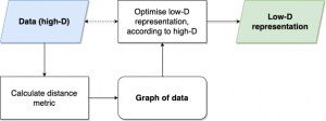
The basic process for (most) embedding methods, for example MDS, UMAP and t-SNE

UMAP, TSNE, MDS

What happens when we don’t solve the dimensionality reduction problem with any (well, some) linear algebra? We arrive at the last general group of algorithms we’ll talk about.

These start much the same as Spectral Embedding: by constructing a graph/network of the data. This is done in different ways by each of these algorithms.

Most simple is MDS, which uses just the distance between all points. This is a computationally costly step, as for N points, we have to calculate O(N²) distances.

TSNE does a similar thing as Spectral Embedding, and moves from distance into a weight of connection, which represents the probability that these two points are related. This is normally done using a normal distribution. Unlike Spectral Embedding or UMAP, TSNE doesn’t consider these distances for a given number of neighbours, but instead draws a bubble around itself and gets distances and weights for all the points in that bubble. It’s not quite that simple, but this is already a long article, so check this article by Kemal Erdem for a full walkthrough.

UMAP considers a fixed number of neighbours for each point, like Spectral Embedding, but has a slightly different way of calculating distances. The “Uniform Manifold” in UMAP means that UMAP is assuming that points are actually uniformly distributed, but that the data-space itself is warped, so that points don’t show this.

Again the maths here is difficult, so check the UMAP documentation for a full walkthrough. Be warned, however, that the authors are very thorough in their explanation. As of May 2022, the “how UMAP works” section is over 4500 words.

In UMAP, TSNE and Spectral Embedding, we have a parameter we can use to change how global a view we want the embedding to take. UMAP and Spectral Embedding are fairly intuitive, where we control simply the number neighbours considered, but in TSNE we use perplexity, which kind of like the size of the bubble around each point.

Once these algorithms have a graph with weighted edges, they try and lay out the graph in a lower number of dimensions (for our purposes this is 2D). They do this by trying to optimise according to a given function. This just means that they try and find the best way to place the nodes in our graph in 2D, according to an equation.

For MDS this is “stress”:

Credit goes to Saul Dobilas article on MDS

TSNE first calculated the student-t distribution with a single degree of freedom:

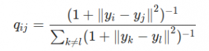
The student-t distribution with one degree of freedom, as used by TSNE

Its important to note in the equation above that all are actually vectors, as in the stress equation, so that with those ||a— b|| partswe’re calculating a kind of distance. here is the similarity between points. From here TSNE uses the Kullback-Leibler divergence of the two graphs to measure their similarity. It all gets very mathsy — check out Kemal Erdem’s article for more information.

UMAP again steps up the maths, and optimises the cross-entropy between the low-D and high-D layouts:

Cross-entropy used by UMAP. Subscript H indicates higher-D, subscript L indicates lower-D

The best explanation of UMAP actually comes from its own documentation. This might be because they don’t distribute it through sklearn.

This can be broken down into a repulsive and attractive “force” between points in the high-D and low-D graphs, so that the layout step acts like a set of atoms in a molecule. Using forces is quite common in graph layouts, and can be intuitive to think about compared to other metrics. It also means that UMAP (in theory) should be able to express both global and local dynamics in the data, depending on your choice of the number of neighbours considered. In practise this means that you can actually draw conclusions about your data from the distance between points across the whole UMAP embedding, including the shape of clusters, unlike TSNE.

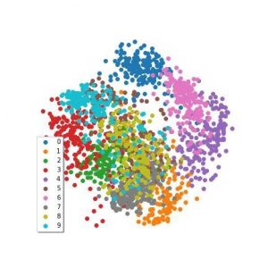
It’s been a while without a figure, so here’s all three applied to the MNIST data:

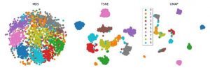
MDS, TSNE and UMAP applied to the sklearn version of the MNIST dataset

We can see that all three seem to have been fairly effective. But how should we understand the results of something that, while optimising the lower-D graph, uses a stochastic (semi-random) process? How do you interpret something that changes based on its random seed? Ideally, we develop an intuition as to how the algorithms function, instead of just knowing the steps of the algorithm.

I’m going to ask you to scroll back up to the top and take another look at the big figure again. Its the last time we do this, I promise.

Firstly, MDS considers all the inter-point relations, so the global shape of data is preserved. You can see this in particular in the first two examples. The inner cube has all of its vertices connected, and the vertices of each cube “line up” with each other (vague, hopefully you see what I mean). There is some disconnection in the edges of the outer cube, and some warping in all the other edges. This might be due to the algorithm trying to preserve distances, but as with all stochastic processes, its difficult to decipher.

UMAP and TSNE also maintain the “lines” of the cube. UMAP is actually successful at separating the two cubes, and makes interesting “exploded diagram” style representations of them. In the UMAP embedding only one of the vertices of each cube is separated. In the TSNE embedding the result isn’t as promising, possibly because the “bubble” drawn by the algorithm around points also catches the points in the other cube.

Both UMAP and TSNE separate the spheres in the second example and the gaussians in the fourth. The “bubble” vs neighbours difference between UMAP and TSNE is also illustrated by the corkscrews example (with a non-default number of neighbours considered by UMAP the result might be more similar). So these algorithms look great! Except there’s always a catch.

Check the final example, which we haven’t touched on before. This is just random noise along each axis. There should be no meaningful pattern in the projections — and the first four algorithms reflect this. SVD, MDS and the Spectral Embedding are actually able to represent the “cube” shape of the data. However, TSNE and UMAP could easily be interpreted as having some pattern or meaning, especially UMAP.

We’ve actually arrived at the classic machine-learning compromise: expressivity vs bias. As the algorithms become more complex, and more able to represent complex dynamics in the data, their propensity to also capture confounding or non-meaningful patterns also becomes greater. UMAP, arguably the most complex of these algorithms, arguably has the greatest expressivity, but also the greatest risk of bias.

Conclusions

So what have we learnt? As algorithms become more complex, they’re more able to express dynamics in the data, but risk also expressing patterns that we don’t want. That’s true all over machine learning, in classification, regression or something else.

Distance-based models with stochastic algorithms (UMAP, TSNE, MDS) represent the relationships between points, and linear-algebra methods (PCA, SVD) take a “global” view, so if you want to make sure that your reduction is true to the data, stick with these.

Parameter choice becomes more important in the newer, stochastic, distance-based models. The corkscrew and cube examples are useful here — a different choice of parameters and we might have had UMAP looking more like TSNE.

BIAS Day 1 Review: ‘Interactive AI’

This review of the 2nd day of the BIAS event, ‘Interactive AI’, is written by CDT Student Vanessa Hanschke

The Bristol Interactive AI Summer School (BIAS) was opened with the topic of ‘Interactive AI’, congruent with the name of the hosting CDT. Three speakers presented three different perspectives on human-AI interactions.

Dr. Martin Porcheron from Swansea University started with his talk “Studying Voice Interfaces in the Home”, looking at AI in one of the most private of all everyday contexts: smart speakers placed in family homes. Using an ethnomethodological approach, Dr. Porcheron and his collaborators recorded and analysed snippets of family interactions with an Amazon Echo. They used a purpose-built device to record conversations before and after activating Alexa. While revealing how the interactions with the conversational AI were embedded in the life of the home, this talk was a great reminder of how messy real life may be compared to the clean input-output expectations AI research can sometimes set. The study was also a good example of the challenge of designing research in a personal space, while respecting the privacy of the research subjects.

Taking a more industrial view of human-AI interactions, Dr Alison Smith-Renner from Dataminr followed with her talk “Designing for the Human-in-the-Loop: Transparency and Control in Interactive ML”. How can people collaborate with an ML (Machine Learning) model to achieve the best outcome? Dr. Smith-Renner used topic modelling to understand the human-in-the-loop problem with respect to these two aspects: (1) Transparency: methods for explaining ML models and their results to humans. And (2) Control: how users can provide feedback to systems. In her work, she looks at how users are affected by the different ways ML can apply their feedback and if model updates are consistent with the behaviour the users anticipate. I found particularly interesting the different expectations the participants of her study had of ML and how the users’ topic expertise influenced how much control they wanted over a model.

Finally, Prof. Ben Shneiderman from the University of Maryland concluded with his session titled “Human-Centered AI: A New Synthesis” giving a broader view on where AI should be heading by building a bridge between HCI (Human-Computer Interaction) and AI. For the question of how AI can be built in a way that enhances people, Prof. Shneiderman presented three answers: the HCAI framework, design metaphors and governance structures, which are featured in his recently published book. Hinting towards day 4’s topic of responsible AI, Prof. Shneiderman drew a compelling comparison between safety in the automobile industry and responsible AI. While often unlimited innovation is used as an excuse for a deregulated industry, regulation demanding higher safety in cars led to an explosion of innovation of safety belts and air bags that the automobile industry is now proud of. The same can be observed for the right to explainability in GDPR and the ensuing innovation in explainable AI. At the end of the talk, Prof. Shneiderman called to AI researchers to create a future that serves humans and is sustainable and “makes the world warmer and kinder”.

It was an inspiring afternoon for anyone interested in the intersection of humans and AI, especially for researchers like me trying to understand how we should design interfaces and interactions, so that we can gain the most benefit as humans from powerful AI systems

BIAS Day 4 Review: ‘Data-Driven AI’

This review of the 4th day of the BIAS event, ‘Data-Driven AI’, is written by CDT Student Stoil Ganev.

The main focus for the final day of BIAS was Data-Driven AI. Out of the 4 pillars of the Interactive AI CDT, the Data-Driven aspect tends to have a more “applied” flavour compared to the rest. This is due to a variety of reasons but most of them can be summed up in the statement that Data-Driven AI is the AI of the present. Most deployed AI algorithms and systems are structured around the idea of data X going in and prediction Y coming out. This paradigm is popular because it easily fits into modern computer system architectures. For all of their complexity, modern at-scale computer systems generally function like data pipelines. One part takes in a portion of data, transforms it and passes it on to another part of the system to perform its own type of transformation. We can see that, in this kind of architecture, a simple “X goes in, Y comes out” AI is easy to integrate, since it will be no different from any other component. Additionally, data is a resource that most organisations have in abundance. Every sensor reading, user interaction or system to system communication can be easily tracked, recorded and compiled into usable chunks of data. In fact, for accountability and transparency reasons, organisations are often required to record and track a lot of this data. As a result, most organisations are left with massive repositories of data, which they are not able to fully utilise. This is why Data-Driven AI is often relied on as a straight forward, low cost solution for capitalising on these massive stores of data. This “applied” aspect of Data-Driven AI was very much present in the talks given at the last day of BIAS. Compared to the other days, the talks of the final day reflected some practical considerations in regards to AI.

The first talk was given by Professor Robert Jenssen from The Arctic University of Norway. It focused on work he had done with his students on automated monitoring of electrical power lines. More specifically how to utilise unmanned aerial vehicles (UAVs) to automatically discover anomalies in the power grid. A point he made in the talk was that the amount of time they spent on engineering efforts was several times larger than the amount spent on novel research. There was no off the shelf product they could use or adapt, so their system had to be written mostly from scratch. In general, this seems to be a pattern with AI systems where even, if the same model is utilised, the resulting system ends up extremely tailored to its own problem and cannot be easily reused for a different problem. They ran into a similar problem with the data set, as well. Given that the problem of monitoring power lines is rather niche, there was no directly applicable data set they could rely on. I found their solution to this problem to be quite clever in its simplicity. Since gathering real world data is rather difficult, they opted to simulate their data set. They used 3D modelling software to replicate the environment of the power lines. Given that most power masts sit in the middle of fields, that environment is easy to simulate. For more complicated problems such as autonomous driving, this simulation approach is not feasible. It is impossible to properly simulate human behaviour, which the AI would need to model, and there is a large variety in urban settings as well. However, for a mast sitting in a field, you can capture most of the variety by changing the texture of the ground. Additionally, this approach has advantages over real world data as well. There are types of anomalies that are so rare that they might simply not be captured by the data gathering process or be too rare for the model to notice them. However, in simulation, it is easy to introduce any type of anomaly and ensure it has proper representation in the data set. In terms of the architecture of the system, they opted to structure it as a pipeline of sub-tasks. There are separate models for component detection, anomaly detection, etc. This piecewise approach is very sensible given that most anomalies are most likely independent of each other. Additionally, the more specific a problem is, the easier and faster it is to train a model for it. However, this approach tends to have larger engineering overheads. Due to the larger amount of components, proper communication and synchronisation between them needs to be ensured and is not a given. Also, depending on the length of the pipeline, it might become difficult to ensure that it perform fast enough. In general I think that the work Professor Jenssen and his students did in this project is very much representative of what deploying AI systems in the real world is like. Often your problem is so niche that there are no readily available solutions or data sets, so a majority of the work has to be done from scratch. Additionally, even if there is limited or even no need for novel AI research, a problem might still require large amounts of engineering efforts to solve.

The second talk of the day was given by Jonas Pfeiffer, a PhD student from the Technical University of Darmstadt. In this talk he introduced us to his research on Adapters for Transformer models. Adapters are a light weight and faster approach to fine tuning Transformer models to different tasks. The idea is rather simple, the Adapters are small layers that are added between the Transformer layers, which are trained during fine tuning, while keeping the transformer layers fixed. While pretty simple and straight forward, this approach appears to be rather effective. However, other than focusing on his research on Adapters, Jonas is also one of the main contributors to AdapterHub.ml, a framework for training and sharing Adapters. This brings our focus to an important part of what is necessary to get AI research out of the papers and into the real world – creating accessible and easy to use programming libraries. We as researchers often neglect this step or consider it to be beyond our responsibilities. That is not without sensible reasons. A programming library is not just the code it contains. It requires training materials for new users, tracking of bugs and feature requests, maintaining and following a development road map, managing integrations with other libraries that are dependencies or dependers, etc. All of these aspects require significant efforts by the maintainers of the library. Efforts that do not contribute to research output and consequently do not contribute to the criteria by which we are judged as successful scientists. As such, it is always a delight when you see a researcher willing to go this extra mile, to make his or her research more accessible. The talk by Jonas also had a tutorial section where he led us though the process of fine tuning an off the shelf pre-trained Transformer. This tutorial was delivered through Jupyter notebooks easily accessible from the projects website. Within minutes we had our own working examples, for us to dissect and experiment with. Given that Adapters and the AdapterHub.ml framework are very recent innovations, the amount and the quality of documentation and training resources within this project is highly impressive. Adapters and the AdapterHub.ml framework are excellent tools that, I believe, will be useful to me in the future. As such, I am very pleased to have attended this talk and to have discovered these tools though it.

The final day of BIAS was an excellent wrap up to the summer school. With its more applied focus, it showed us how the research we are conducting can be translated to the real world and how it can have an impact. We got a flavour of both, what it is like to develop and deploy an AI system, and what it is like to provide a programming library for our developed methods. These are all aspects of our research that we often neglect or overlook. Thus, this day served as great reminder that our research is not something confined within a lab but that it is work that lives and breathes within the context of the world that surrounds us.

BIAS Day 3 Review: ‘Responsible AI’

This review of the 3rd day of the BIAS event, ‘Responsible AI’, is written by CDT Student Emily Vosper. 

Monday was met with a swift 9:30am start, made easier to digest with a talk on AI and Ethics, why all the fuss? By Toby Walsh. This talk, and subsequent discussion, covered the thought-provoking topic of fairness within AI. The main lesson considered whether we actually need new ethical principles to govern AI, or whether we can take inspiration from well-established areas, such as medicine. Medicine works by four key principles: Beneficence, non-maleficence, autonomy and justice and AI brings some new challenges to this framework. The new challenges include autonomy, decision making and culpability. Some interesting discussions were had around reproducing historical biases when using autonomous systems, for example within the justice system such as predictive policing or parole decision making (COMPAS).

The second talk of the day was given by Nirav Ajmeri and Pradeep MuruKannaiah on ethics in sociotechnical systems. They broke down the definition of ethics as distinguishing between right and wrong which is a complex problem full of ethical dilemmas. Such dilemmas include examples such as Les Miserables where the actor steals a loaf of bread, stealing is obviously bad, but the bread is being stollen to feed a child and therefore the notion of right and wrong becomes nontrivial. Nirav and Pradeep treated ethics as a multiagent concern and values were brought in as the building blocks of ethics. Using this values-based approach the notion of right and wrong could be more easily broken down in a domain context i.e. by discovering what the main values and social norms are for a certain domain rules can be drawn up to better understand how to reach a goal within that domain. After the talk there were some thought provoking discussions surrounding how to facilitate reasoning at both the individual and the societal level, and how to satisfy values such as privacy.

In the afternoon session, Kacper Sokol ran a practical machine learning explainability session where he introduced the concept of Surrogate Explainers – explainers that are not model specific and can therefore be used in many applications. The key takeaways are that such diagnostic tools only become explainers when their properties and outputs are well understood and that explainers are not monolithic entities – they are complex with many parameters and need to be tailer made or configured for the application in hand.

The practical involved trying to break the explainer. The idea was to move the meaningful splits of the explainer so that they were impure, i.e. they contain many different classes from the black box model predictions. Moving the splits means the explainer doesn’t capture the black box model as well, as a mixture of points from several class predictions have been introduced to the explainer. Based on these insights it would be possible to manipulate the explainer with very impure hyper rectangles. We found this was even more likely with the logistical regression model as it has diagonal decision boundaries, while the explainer has horizontal and vertical meaningful splits.